I never thought I’d be glad to see sines and cosines again. Yet that’s exactly what happened when I started writing my first GLSL shaders. Those trigonometric functions we learned in high school without really knowing what they’d be useful for “in real life.” They’re everywhere in creative development. Oscillations, deformations, periodic animations: trig is the foundation.
This article is a hands-on account. I’m not a shader expert. This is my first solo project after learning the basics of GLSL through Three.js Journey, the official docs, and plenty of examples on Awwwards and Codrops. My approach: learn something, then build something to test what I just learned. No client brief, no ambitious project needed. Just an idea, an npm create command, and off we go.
The result is an infinite 3D image carousel, where each image reacts to scroll and mouse input through shaders. Here’s what it looks like:
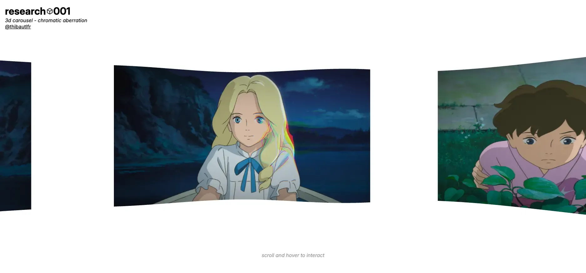
The final render of the carousel with the chromatic aberration effect
The setup: a custom Three.js boilerplate
Before touching shaders, you need a solid foundation. I built my own native Three.js boilerplate: a modular architecture with scene, camera, renderer, resource management, render loop, and debug tools. It lets me focus directly on the actual work without reconfiguring everything for each project. I’ll write a dedicated article about it, but in short: an Experience singleton class orchestrates everything, and each component (camera, world, carousel) is self-contained.
For shaders specifically, I use vite-plugin-glsl which allows importing .glsl files directly into TypeScript. It avoids writing GLSL in template literals and gives you syntax highlighting in the IDE.
The vertex shader: deforming geometry
The vertex shader is the first program that runs in the graphics pipeline. It processes each vertex (corner point) of the geometry and determines its final screen position via gl_Position.
In my case, the carousel images are PlaneGeometry instances with 32×32 subdivisions, meaning over 1,000 vertices per image. Enough for smooth deformations.
Here’s the complete vertex shader:
uniform vec2 uFrequency;
uniform float uTime;

varying vec2 vUv;
varying float vElevation;

void main() {
  vec4 modelPosition = modelMatrix * vec4(position, 1.0);

  float elevation = sin(modelPosition.x * uFrequency.x) * 0.1;
  elevation += sin(modelPosition.y * uFrequency.y) * 0.1;
  modelPosition.z += elevation;

  vec4 viewPosition = viewMatrix * modelPosition;
  vec4 projectedPosition = projectionMatrix * viewPosition;

  gl_Position = projectedPosition;

  vUv = uv;
  vElevation = elevation;
}
A few key concepts here:
- Uniforms (
uFrequency,uTime) are values sent from JavaScript. They’re identical for all vertices of a given mesh, hence the name “uniform” - Varyings (
vUv,vElevation) are values computed in the vertex shader and passed to the fragment shader. The GPU automatically interpolates them between vertices, producing smooth transitions - The
modelMatrix → viewMatrix → projectionMatrixchain transforms the vertex’s local coordinates into screen coordinates. This is the standard Three.js pipeline
The deformation comes from these two lines:
float elevation = sin(modelPosition.x * uFrequency.x) * 0.1;
elevation += sin(modelPosition.y * uFrequency.y) * 0.1;
sin() applied to the vertex’s X position produces a wave along the image. uFrequency controls the “density” of that wave. With uFrequency.x = 3.5 and uFrequency.y = 0, you get a subtle horizontal deformation that gives depth to the images. And that’s where high school trigonometry resurfaces: a simple sine oscillating between -1 and 1, multiplied by 0.1 to limit the amplitude. No magic, just basic math applied in a visual context.
The fragment shader: controlling each color channel
The fragment shader runs after the vertex shader. For each fragment (a fragment roughly corresponds to a pixel on screen, but before depth testing and blending), it determines the final color via gl_FragColor.
This is where it gets interesting. With texture2D(uTexture, vUv), we sample the image texture at UV coordinates interpolated from the vertex shader. The result is a vec4: four components for red, green, blue, and alpha. And you can manipulate each channel independently.
uniform sampler2D uTexture;
uniform float uVignetteOffset;
uniform float uVignetteDarkness;
uniform vec2 uMouse;
uniform vec2 uResolution;
uniform float uStereoRadius;
uniform float uStereoStrength;
varying vec2 vUv;

void main() {
    vec2 screenUv = gl_FragCoord.xy / uResolution;

    float aspect = uResolution.x / uResolution.y;
    vec2 diff = screenUv - uMouse;
    diff.x *= aspect;

    float dist = length(diff);

    float mask = smoothstep(uStereoRadius, 0.0, dist);

    vec2 dir = dist > 0.001 ? normalize(diff) : vec2(0.0);

    vec2 uvOffset = dir * uStereoStrength * mask;
    uvOffset.x /= aspect;

    float r = texture2D(uTexture, vUv + uvOffset).r;
    float g = texture2D(uTexture, vUv).g;
    float b = texture2D(uTexture, vUv - uvOffset).b;
    float a = texture2D(uTexture, vUv).a;

    vec4 color = vec4(r, g, b, a);

    vec2 uv = (vUv - vec2(0.5)) * vec2(uVignetteOffset);
    color.rgb *= 1.0 - dot(uv, uv) * uVignetteDarkness;

    gl_FragColor = color;
}
It’s denser than the vertex shader, but the logic breaks down into two distinct effects: chromatic aberration and vignette.
Chromatic aberration: a happy accident
Chromatic aberration is that color-shifting effect often seen in video games or photography, when the red, green, and blue channels are no longer perfectly aligned. In real optics, it’s a lens defect. In creative dev, it’s an effect we reproduce on purpose because it looks great.
It wasn’t planned for my project. While exploring the fragment shader, I realized you could sample the texture at different UV coordinates for each channel. The breakthrough: if I shift red in one direction and blue in the other, while keeping green centered, I get exactly that chromatic separation effect.
float r = texture2D(uTexture, vUv + uvOffset).r;
float g = texture2D(uTexture, vUv).g;
float b = texture2D(uTexture, vUv - uvOffset).b;
Three texture2D calls, three different coordinates. The red channel is sampled “ahead” of the offset, green at the center, blue “behind.” That’s it. Three lines for an effect that looks far more complex than it actually is.
Making it dynamic with the mouse
The next idea was to make the effect interactive rather than static, by tying it to the cursor position. To do that, I send the normalized mouse coordinates as a uMouse uniform from JavaScript:
private handleMouseMove = (e: MouseEvent) => {
    this.mouse.x = e.clientX / window.innerWidth;
    this.mouse.y = 1.0 - e.clientY / window.innerHeight;
};
On the shader side, I compute the distance between each fragment and the mouse position on screen. smoothstep creates a radial mask: the effect is strongest at the cursor’s center and fades out progressively.
float dist = length(diff);
float mask = smoothstep(uStereoRadius, 0.0, dist);
uStereoRadius controls the size of the effect zone, uStereoStrength its intensity. As you move the mouse over the carousel, the aberration follows the cursor like a distortion lens. It’s the kind of interactive detail that makes a web experience memorable.
Vignette as a bonus
The vignette is simpler: we darken the edges of each image based on the distance from the UV center.
vec2 uv = (vUv - vec2(0.5)) * vec2(uVignetteOffset);
color.rgb *= 1.0 - dot(uv, uv) * uVignetteDarkness;
dot(uv, uv) gives the squared distance from the center. The further from the center, the higher the value, the more the colors are attenuated. It gives each carousel image a natural framing.
The infinite carousel
The carousel itself is a matter of circular layout and simple physics. Images are placed in a circle using, once again, trig:
for (let i = 0; i < count; i++) {
  const image = new Image(this.textures[i]);
  const angle = (i / count) * Math.PI * 2;

  image.mesh.position.x = Math.sin(angle) * radius;
  image.mesh.position.z = Math.cos(angle) * radius;
  image.mesh.lookAt(0, 0, 0);

  this.group.add(image.mesh);
}
Each image is positioned on the circle with sin and cos, then oriented toward the center with lookAt. Scrolling (or swiping on mobile) adds velocity to the group’s rotation, slowed by a friction coefficient. When you stop interacting, the carousel keeps spinning gently, a subtle auto-rotation that keeps the experience alive.
What I took away
GLSL shaders are less obscure than they look. The vertex shader transforms positions, the fragment shader transforms colors. With uniforms to pass data from JavaScript and varyings to communicate between the two, you have everything you need to create custom visual effects.
What struck me most is how simple concepts (a sine, a distance, a dot product) are enough to produce visually rich results. The chromatic aberration that emerged from simple experimentation with RGB channels is proof of that.
If you’re hesitating to get into shaders, start small. A PlaneGeometry, a ShaderMaterial, and a sin() in the vertex shader. Deform something, change a color, add a uniform that moves with time. That’s how you learn. By breaking pixels.